My most recent advancement in the area of rocketry has been to explore making my own motors.
These are photos of a recent expedition to learn this skill from some experienced folks:
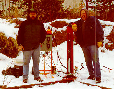
Some of my mentors in this endevour are Bob and Carl:

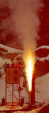
Here they are just before a successful test of their J motor using a new propellant formulation in their standard 54mm aluminum test casing.
 (Photo
taken with 200mm zoom lens from behind barracade, then enlarged.)
It worked perfectly! Unfortunately, the chamber pressure sensor was damaged during this test and the test of another motor had to be postponed.
See the video
of this test (1 MB .mpg file).
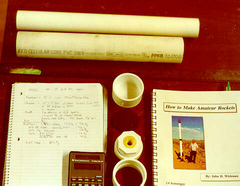
Then it was my turn. I chose the standard AN/Mg propellant formula from John Wickman's book and based my overall design on one of his sample plans. PVC is a nice choice for the structure of a first motor if you are careful not to overpressurize it. Bob and Carl already had cast some Durham's Water Putty into PVC pieces so I decided to use one of those for my nozzle and planned a 2" PVC motor with 15" combustion chamber. I wanted it to be a J or K class motor.
It took several simulation runs to decide the grain and nozzle geometry. Schedule 40 PVC is limited to 300psi, so a multi-grain geometry with an unusually large nozzle throat was selected to keep the chamber pressure down around 250psi. Five grains of 3" each were used. Total propellant weight was just under 1.5lbs so we made a batch of 1.75 lbs to leave a bit to spare and for Atmospheric Pressure Combustibility testing. The resulting design predicted a mid-range K class total impulse with a very flat pressure and thrust curve and a 4.25 second burn time. This would be almost twice the power of my largest motor fired yet to date, an Aerotech J350W on my Level 2 High Power Certification flight!

[Warning: Do not try to duplicate this motor just
from this basic description (or any web site).
Buy the books, take a class, join an organization,
study, do the calculations, and learn slowly and carefully.
If you don't have the time, maturity,
or money to do this correctly, then don't do it; you could be hurt or killed..]
So here are the final motor specs: (Note PVC components are measured
by Inside Diameter)
Propellant:
Solid Composite: 80% solids. Cast with 3/4" core.
Casing:
2"id PVC Sched 40 pipe, 15" long (should have been 1/8" longer to give
more slack between the grains)
Casting Tubes Cardboard tube (17"
Kosdon 54mm motor Liner tubing, made by LOC?). Later cut into five
3" grains, with a bit left over.
Insulation:
EDM rubber liner and 3000deg Oven Gasket Sealer as insulation.
Nozzle:
Durham's Water Putty cast into a 1.5" to 1/2" (actaully larger since 1/2"
is the interior pipe diameter) threaded PVC fitting,
drilled out to 31/64" (.484"), with an exit cone of 5/8". (sub optimal,
but I didn't have any more room in the fitting).
Aft Closure:
1.5" to 2" adapter ring fit the nozzle into a 2" PVC coupler.
Forward Closure: Originally planned to be a simple 2" PVC cap
but I decided to add a pressure guage tap so used a 2" to 1.5" transition
to
a 1.5" to 3/4" threaded fitting insulated with a cylinder and donut of
EDM rubber + gasket cement.
When the pressure guage was damaged in an earlier test, I ended up just
plugging this port with a 3/4" threaded steel plug.

The ingrediants were added one at a time (using separate spoons) and
the total batch measured on a triple-beam scale during each step and mixing
in a stainless steel bowl by hand with paint stiring sticks. It is critical
that the Mg be thoroughly wetted with binder before the addition of the
AN. The curative was measured separately in a small plastic cup so
it could be added at the last moment before the final mix:

Here Bob poses with the new vacuum mixer. He is so excited about this new mixer that he was uncontrollable. There are two view ports so we have a light shining in one and a video camera pointing in the other so we can watch the progress on the tv monitor without having to stand so close.
The propellant was mixed for 60 minutes, then we spent about 30 minutes packing it into the casting tube using a nice fixture that Carl made to hold the casting tube vertical and keep the core mandrel centered. The mandrel was wrapped with a thin plastic so it could be slipped out easily later. The propellant's binder was just starting to set up as we finished. It was allowed to dry overnight. The assembly of the motor the next day proceded very smoothly and the PVC cement was alowed to dry for another day.
All tools were cleaned with WD-40 followed by a wipe down with Isopropyl
Alcohol. We used a LOT of paper towels.

The test firing of my motor was quite an experience. That night I had made a list of a half-dozen reasons I thought it would fail, so was extra careful about the test setup and safety. Besides being strapped to the steel test stand, it was also enclosed by a 4" stainless steel pipe to catch any shrapnel. The whole test site is enclosed by an earthen berm. The test was videoed but not instrumented since I didn't want to risk damage to the load-cell until sure of the overall performance of the design. Especially since we'd already trashed the pressure sensor on an earlier test.

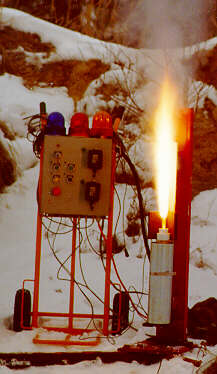
The burn was interesting. See the video (2MB .mpg). It took a bit longer to get up to pressure than Bob and Carl's "J" had the previous day and did not have nearly as much flame. Everything held together fine but the burn was a bit unstable and made a visual and audible pulsation. The burn lasted for a very long time, around 18 seconds. Later examination showed that the 31/64" nozzle throat had erroded to about 3/4", actually the same as the nozzle exit, although part of the exit cone remained smaller. This nozzle enlargement could have been partially responsible for the extra-long burn.
From the photo above you can see that the flame is coming out straight before expanding. I think this means that my nozzle wasn't long enough (again due to me thinking it needed to have such a large throat). The reason I made the nozzle throat just shy of 1/2" was that the simulations using FPRED software were run using the burn rate parameters for -1000mesh magnesium. John Wickman later pointed out that Pyrotek's Mg was better modeled using the parameters for "-650 prill". Further exaggerating the error is that the Durham's putty eroded at about twice the rate I expected. Then there was the grain core to nozzle area ratio which was too small so I probably had erosive burning of the propellant. Another factor was that the grains were rather tight in the case and may not have had enough free end-play to burn efficiently at the segment ends during the early part of the burn. Also, the ignitor may have been allowed to drop past the end of the grains, into the pressure sensor fitting coupler, resulting in a chuffy ignition.
What a learning experience! Sometimes its the things you do wrong that teach you the most.
Simulations run afterwards with the new information now matched the
test results very well and showed that my motor was only a mid-range J50
and probably never built up more than 100psi chamber pressure and 30lbs
thrust.
The postmortem showed that everything was fine internally:

In fact, the PVC held up so well, that I'll try making a reusable threaded PVC casing for ground testing. Then I could have interchangable chamber lengths, nozzle sizes, etc and save some money and lots of time.
I'll try to repeat this design with a better simulation parameters,
slightly lower binder percentage, more slack between grains, and a phenolic
or graphite nozzle insert.
Overall it was an awesome experience! Thanks Bob and Carl!